An article titled "Trilobite-inspired neural nanophotonic light-field camera with extreme depth-of-field" by Q. Fan et al. proposes a metalens design inspired by the bi-focal vision system of an extinct marine arthropod.
Abstract
A unique bifocal compound eye visual system found in the now extinct trilobite, Dalmanitina socialis, may enable them to be sensitive to the light-field information and simultaneously perceive both close and distant objects in the environment. Here, inspired by the optical structure of their eyes, we demonstrate a nanophotonic light-field camera incorporating a spin-multiplexed bifocal metalens array capable of capturing high-resolution light-field images over a record depth-of-field ranging from centimeter to kilometer scale, simultaneously enabling macro and telephoto modes in a snapshot imaging. By leveraging a multi-scale convolutional neural network-based reconstruction algorithm, optical aberrations induced by the metalens are eliminated, thereby significantly relaxing the design and performance limitations on metasurface optics. The elegant integration of nanophotonic technology with computational photography achieved here is expected to aid development of future high-performance imaging systems.
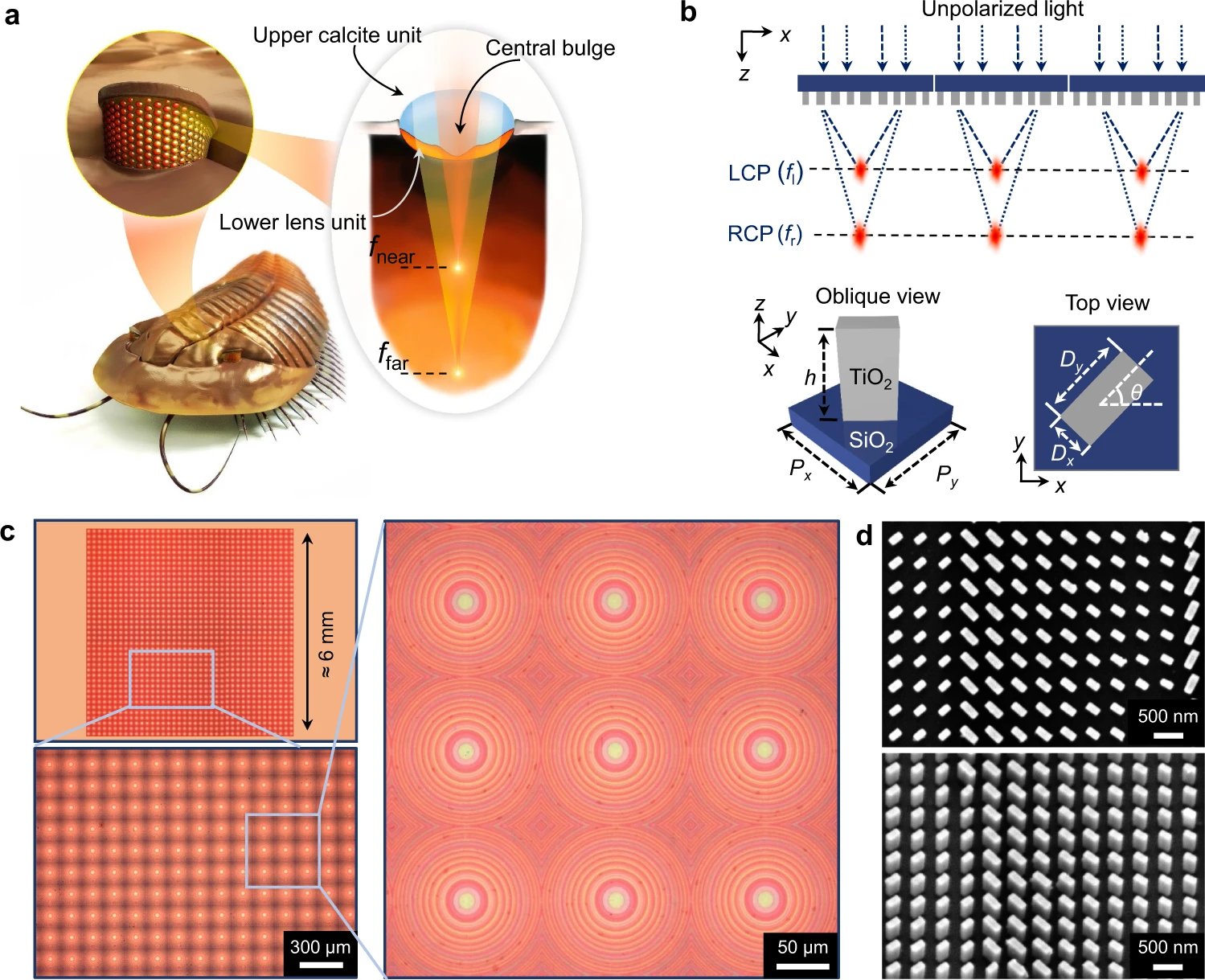
a Conceptual sketch of extinct trilobite Dalmanitina socialis and its compound eyes. Each compound eye, composed of a lower lens unit and an upper lens unit with central bulge, can simultaneously focus the incident light to near and far point, similar to a coaxial bifocal lens. b The bioinspired photonic spin-multiplexed metalens array. The unit cell of metalens array is composed of rectangle amorphous TiO2 nanopillar sitting on a SiO2 substrate with Px=Py=450 nm, and height h=600 nm. c Optical microscope image of the fabricated metalens array. The right panel shows a zoomed-in image of 3 × 3 submetalens array. d The scanning electron microscopy (SEM) images show the top view and oblique view of the TiO2 nanopillars.
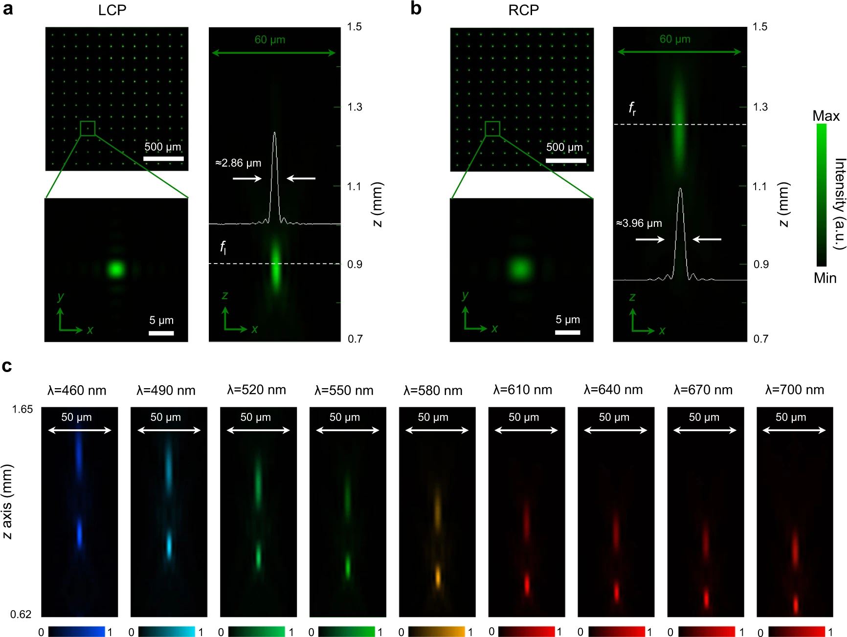
Focal spots in the x-y and x-z plane for (a) LCP and (b) RCP incident light at the wavelength of 530 nm. For ease-of-viewing, here we show an array of 12 × 12 focal spots (top left). The solid white lines show the horizontal cuts of the intensity distributions of focal spots. c Dispersion of a single submetalens illustrated by metalens focusing at different focal lengths for the wavelength spanning from 460 nm to 700 nm. The incident light is linearly polarized.
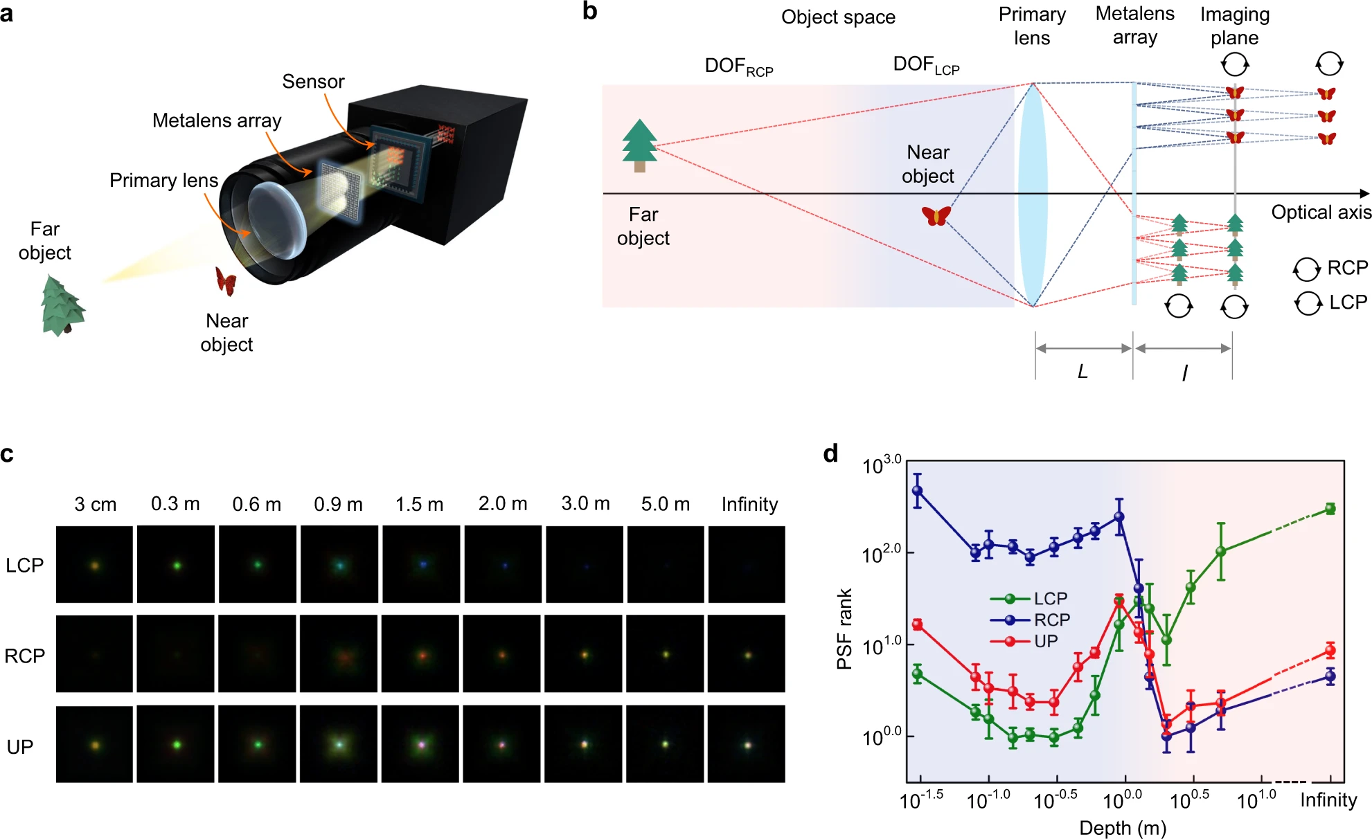
a Conceptual sketch of the proposed light-field imaging camera. b Schematic diagram of the working principle of the system with metalens array achieving spin-dependent bifocal light-field imaging. Either the LCP component of close object or the RCP component of distant object could be focused well on the identical imaging plane. The nominal distance between the primary lens and metalens array is L=47.5 mm. The nominal distance between the imaging plane and metalens array is l=0.83 mm. The focal length and aperture size of the primary lens is F=50 mm and D=6 mm, respectively. c The captured PSFs at different depths for LCP, RCP, and UP (unpolarized) incident light. d Demonstration of working range for different polarization states. The light-blue region and light-red region represent the working range of LCP and RCP components, respectively. The vertical axis represents the PSF ranks, for which the smaller value corresponds to better imaging quality. The uncertainties are standard deviation for repeated measurements (six in total).
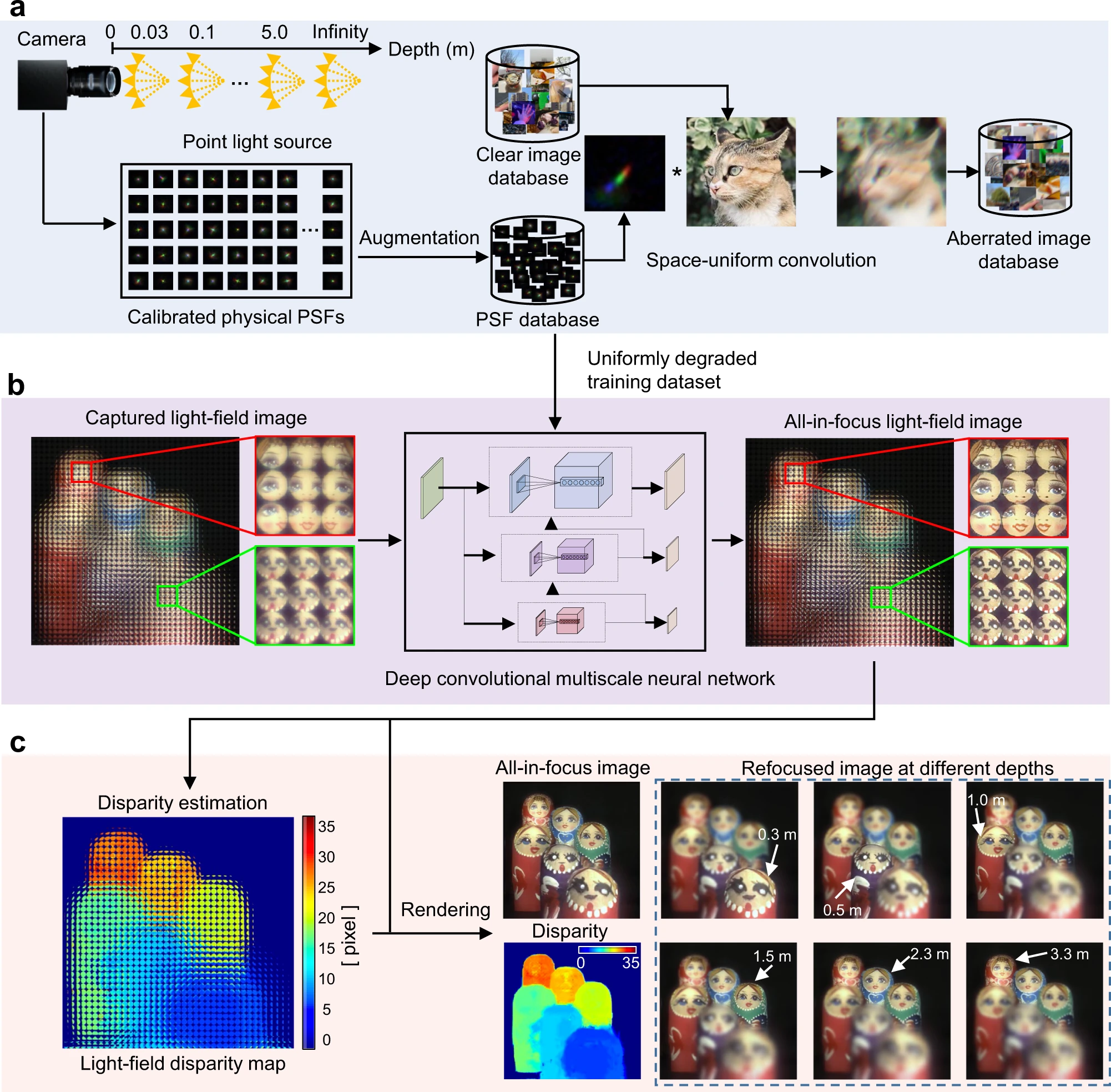
a PSF capture and training-data generation. b Aberration removal with the proposed multiscale deep convolutional neural network. The distance between the primary lens and Matryoshka nesting dolls: 0.3 m, 0.5 m, 1.0 m, 1.5 m, 2.3 m, and 3.3 m. The insets show the nearest and farthest Matryoshka nesting dolls. c Light-field processing based on the retrieved all-in-focus light-field images, including disparity estimation and refocusing images at different depths.
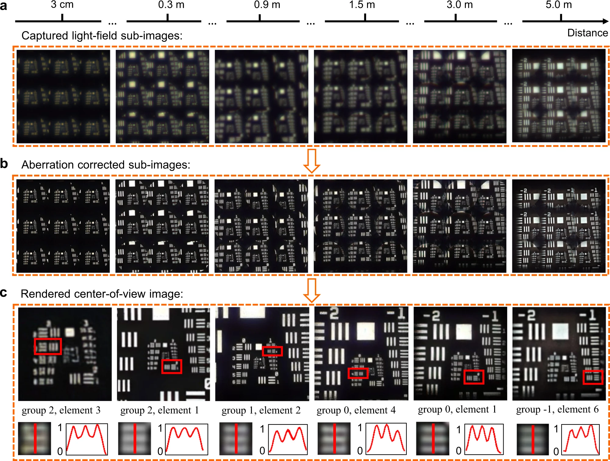
a Captured subimages of a USAF 1951 resolution chart at different depths. For easy recognition, here we show the 3×3 subimages. b Aberration-corrected subimages. c Top: Rendered center-of-view images of the USAF 1951 resolution chart. Bottom: Zoom-in images and intensity cross sections of each smallest-resolvable line pair in the resolution chart.
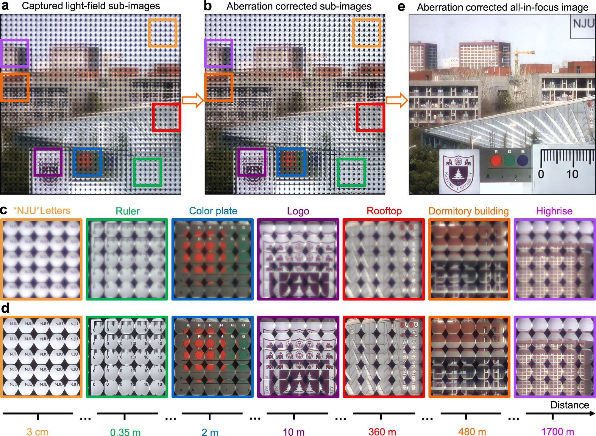
a, b Captured light-field subimages of the whole scene under natural light (a) before and (b) after aberration correction. c, d Zoomed-in subimages of different objects corresponding to the marked ones shown in (a, b), respectively. e Aberration-corrected all-in-focus image after rendering. The reconstructed NJU characters have been reasonably shifted and scaled for easy viewing.
No comments:
Post a Comment
All comments are moderated to avoid spam and personal attacks.